1 INTRODUCTION
Floating Production Storage and
Offloading (FPSO) are floating oil and gas rigs used worldwide in exploration
and production (E&P) projects. These oil rigs have a shipshape hull
structure, many of them are built from existing ships that have been taken out
of service, therefore they have undergone conversion engineering work from ship
to FPSO structure. They are equipped with large structures above the main deck,
namely topsides, where the equipment for the E&P is installed. In the past
two decades, the size and complexity of the topsides have remarkedly grown, and
with it, the static and dynamic loads have grown considerably. In addition,
FPSOs are typically converted oil tankers or purpose-built vessels that are
moored to the seabed using a spread mooring system or a turret mooring system.
The wave load periodically acts on the ship’s hull, making structural integrity
a critical aspect of FPSO design and operation[1]. In the past two decades,
there has been an increased focus on the structural integrity of FPSOs, and
organizations such as The Welding Institute (TWI) have conducted assessments to
ensure the safety and reliability of these structures[2].
Structural integrity is paramount in
FPSOs due to their exposure to harsh environmental conditions and potentially
catastrophic failure. Weld flaws, fatigue, and fracture are some of the most
common issues that can compromise the structural integrity of FPSOs. The design
process of welded structures must carefully consider fatigue failure in
assessing structural integrity[3]. Procedures such as fracture and
fatigue assessments outlined in BS 7910[4] are applied to welded
structures to assess weld flaws. Additionally, methodologies like the
Engineering Critical Assessment (ECA), proposed by TWI structural integrity
group, is capable to assess the structural integrity of FPSOs and identify
potential critical joints, whilst proposing mitigation actions to improve the
integrity of the joints [2,3]. The continued focus on the
structural integrity of FPSOs will be essential in ensuring the safety and
reliability of these structures in the future[5]. The ECA methodology can
be used to evaluate the structural integrity of the welds and determine their
fitness for service[6].
Various types of weld flaws can occur
in FPSO vessels, including lack of fusion, porosity, cracks, and inclusions[2]. These flaws can weaken
the weld and reduce its load-bearing capacity, potentially leading to fatigue
and fracture failures[3]. Therefore, it is crucial to
understand the significance of these flaws on structural details and how to
detect and prevent them.
The causes of weld flaws in FPSO
vessels can be attributed to various factors, including welding process
parameters, material properties, and environmental conditions[2]. Welding flaws can occur
due to improper welding techniques, such as inadequate preheating or post-weld
heat treatment. Furthermore, hydrogen in the weld zone can also lead to
cracking and porosity. Environmental factors, such as exposure to saltwater and
corrosive chemicals, can also contribute to developing weld flaws in FPSO
vessels during operation[3].
The detection and prevention of weld
flaws in FPSO vessels are essential to ensure their structural integrity and
safety. Non-destructive examination (NDE) techniques, such as ultrasonic
testing and radiography, can detect weld flaws and assess their severity[2].Preventative measures,
such as proper welding techniques, material selection, and corrosion
protection, can also be implemented to minimize the occurrence of weld flaws in
FPSO vessels[5].
On the other hand, fatigue is of significant
concern in the design and operation of FPSOs. Fatigue failure occurs when a
material is subjected to repeated loading and unloading, which can result in
the formation and propagation of cracks, ultimately leading to structural
failure[3]. The main causes of fatigue in FPSO vessels include wave
induced cyclic loading and structural vibration [2]. Therefore, it is crucial
to assess the fatigue life of FPSO structures to ensure their long-term
integrity and safety.
The fatigue life assessment of FPSO
structures involves analysing the stress history of the vessel and determining
the number of loading cycles the structure can withstand before failure.
Assessing fatigue life is important for determining the inspection and
maintenance requirements of FPSO structures and ensuring their long-term
structural integrity[6].
Mitigation measures for fatigue in
FPSO structures include using high-strength materials, optimizing the design to
reduce stress concentrations, and implementing effective inspection and
maintenance programs[2]. In addition, engineering critical assessment
techniques can help identify potential weld flaws and assess their significance
on fatigue life[7]. These measures can help to ensure the safe and reliable
operation of FPSO structures, protecting the environment and the personnel
working on these vessels.
In addition, fracture processes are a
critical issue in the structural integrity of FPSOs. Two types of fractures can
occur in FPSOs: 1) brittle fracture and 2) ductile fracture. Brittle fracture
occurs suddenly and without warning, while ductile fracture occurs more slowly and
are likely to give warning signs before they actually happen[2]. Both types of fractures
can have severe consequences for the safety and operability of the FPSOs.
The ECA approach[3], based on methods
from BS7910[4], is commonly used in the
offshore industry to assess the structural integrity of FPSOs. It involves, in
the case of static loading, determining the critical flaw size, which depends
on the material’s fracture toughness of the joints under investigation, and
comparing the results with existing flaws detected during non-destructive
examination (NDE). If the detected flaws is smaller in size then the determined
by the ECA the structure is safe to operate. Considerable research has been
conducted on the fracture toughness of marine welded steels and their service
structures to better understand the behaviour of fracture and fatigue crack
growth[7]. By employing ECA methods, it is possible to assess the
structural integrity of FPSOs and ensure their safe and reliable operation[8].
The British Standard BS7910 methods
combined to ECA are widely used for assessing the structural integrity of
welded structures. BS7910 provides guidelines for assessing the risk of fracture
and fatigue failure in welded structures. [9]. ECA is a methodology that
makes use of fracture mechanics theory to determine the significance of welding
flaws, allowing to carry out quantitative estimations of the risk of materials’
failure by fracture and fatigue, especially for existing flaws on welded
structures, as is the case in many FPSO projects[10–12].
The importance of structural integrity
assessment in FPSOs cannot be overstated. NDE aim to detect flaws and their
sizing and are applied during manufacturing and operation of FPSOs [13].
To withstand the
topside loads, converted FPSOs require extensive stiffening of the deck
structure and the connecting structures of the topside stools. It is the stool
that will transfer the static and dynamic loads generated at the topsides to
the hull, conversely, it also receives loads from the hull. The shape of the
stools varies from project to project, but these are welded structures prone to
contain welded flaws. Full weld NDE is prescribed for the stools, nonetheless,
it is well known that all NDE techniques have limitations on the detectable
flaw sizes as the probability of detection (POD) research has demonstrated [14,15,16,17]. To carry
out a reliable ECA, as prescribed in BS7910 [4],
trustworthy input data, e.g., material properties, flaw size, and applied local
stress intensity, is required. In this sense, a case study of the structural
integrity of welded joints of FPSO Module Stools is presented and discussed in
detail.
2 METHODOLOGY
2.1 IDENTIFYING THE engineering challenge
The Engineering
Procurement and Construction (EPC) Group presented concerns regarding the
structural assembly deviations from the project found during the quality
control inspection of the parts manufactured by a subcontractor. A site visit
to the construction site revealed the existence of generalized misalignments of
stiffeners, that were part of load-carrying cruciform joints at the topside
stools, and unexpected thickness changes in the connection joints between the
diamond plates and the lower correspondent plate of the I beam of the pancake
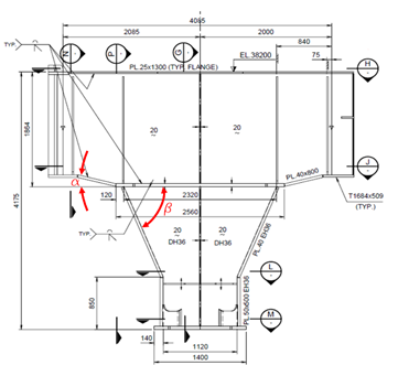
structures. In Figure 1 it is shown the locations of concern, with joints
containing misalignment and thickness changes, Figure 2 shows irregular slope
associated with underfill of the welds, and Figure 3 shows typical superior
stiffener of cruciform join misaligned with stool plate center line.
From the evidence found, a thorough appraisal of the non-conformities, presented by the quality control team of
the EPC Group, was undertaken. The main findings were as follows.
a) During
manufacturing at the subcontractor, considerable buttering was carried out to
correct imperfect joint preparation and/or misassembling of the stool parts related
to the diamond plate.
b) A
subcontractor made considerable non-reported buttering to correct bevel
geometry at several structural details, e.g., columns.
c) The EPC
Group inspection team found several welding imperfections (cracks, inclusions,
blow holes, etc.) at buttered bevels made by the subcontractor, leading to
rework and correction of them prior to welding at the construction site.
Figure 1 – Pancake structure, stool,
and target welded joints marked with red circles.
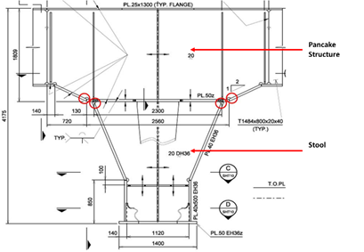
Source: Authors.
Figure 2 – Change
of thickness joint between diamond plate and pancake structure.
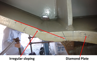
Source: Authors.
Figure
3 – Misalignment
between stool plate and stiffener above the diamond plate.
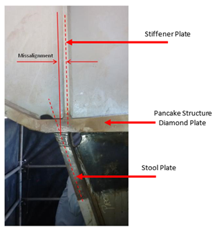
Source: Authors.
Although buttering operations were accepted
by the project as a corrective action to rectify dimensional problems found
during structural assembling, it must be noted that uncontrolled buttering
interventions may leave behind unexpected welding flaws that, if not found
during the inspection, might have as consequence imperfect welds. The EPC Group
welding engineering team reported that a significant amount of weld
discontinuities was found during ultrasonic (UT) inspection at the buttered
bevel preparation made by the subcontractor, leading to unexpected weld
repairs.
2.2 STRATEGY TO SOLVE THE PROBLEM
The EPC Group management team was concerned about the
structural integrity of topsides during the operation of the FPSO, hence
requested that an ECA be undertaken in critical joints defined by their
engineering team. The EPC Group engineering team had concerns about the fatigue
endurance of welded joints of the stool and diamond plate connecting with the I
beam of the pancake plates. They carried out a thorough dimensional inspection
of these welded details and reassessed the fatigue life of the joints to verify
how the reported deviations from the acceptable project tolerances would affect
the fatigue life of the joints. Misalignment and thickness of plates were
studied with consequent recommended corrective measures to achieve project
joint fatigue lives. Nevertheless, the work undertaken only considered standard
SN curve fatigue assessments, no consideration was made for fatigue crack
growth assessment from unknown planar discontinuities that might not have been
detected during NDE in these joints.
Considering the existing knowledge of the POD related
to the NDE techniques used by the EPC Group inspection team, an ECA was carried
out in accordance with BS7910 for the stool cruciform joints and the change of
thickness joints connecting the I beam to the diamond plate. For this regard,
the EPC Group selected the most critical fatigue endurance joints to be
assessed by the ECA.
The main concern
regarding the cruciform joints was the effect of the misalignment of the
stiffener above the diamond plate over the combined fatigue-fracture behaviour
of the joint containing small discontinuities. Similarly, for the butt welds
with the change of thickness, the effect of the subcontractor's non-standard
thickness transition over the joints' fatigue-fracture behaviour. The local
stresses and the fatigue loads considered in the ECA were the as-build fatigue
load spectrum of the joints estimated by the EPC Group engineering team.
Initial flaw sizes considered were the limits of detectability of the NDE
technique in accordance with corresponding POD curves with 80% confidence.
2.3 STOOL CRUCIFORM JOINTS
Five joints were assessed to estimate their fatigue
lives, subjected to the fatigue loading spectrum for each joint, and
considering an existing undetectable surface flaw located at the weld toe. The parameters
employed in the ECA were as follows for all joints: 1-) Level 2
assessment in accordance with BS7910; 2-) fracture Toughness from charpy
correlation to KIC from BS7910:2005 used; charpy-V values
taken from four sets of tests undertaken from a weld prepared by EPC Group
welding engineering team that was made without pre-heat and no interpass
temperature control. The Charpy-V value used had a value of 100 J; analysis and
Charpy testing temperature used was the project minimum allowed operational
temperature of 0o C; KIC
calculated from BS7910 was 3.753,47305 N/mm2; 3-) misalignment
of the joints in the as-built condition; as built axial misalignment per joint
in three (3) conditions; as built angular misalignment per joint in three (3)
conditions; 4-) environment; in air, painted with epoxy without
corrosion; 5-) initial flaw dimension; type and location: surface crack
at the weld toe; surface semi-elliptical flaw smaller than project acceptable
undercut flaws; hight: 0,1 mm; length: 0,3 mm, and the recommendations of the BS7910:2005
for partial safety factors were employed.
3 RESULTS AND DISCUSSIONS
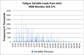
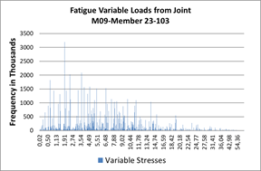
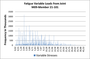
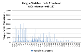
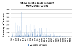
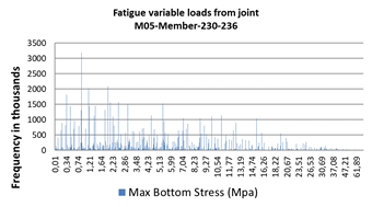
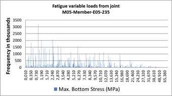
3.1 FATIGUE VARIABLE LOADS
Figure 4 shows the fatigue variable loads provided by the
EPC Group engineering team.
From the fatigue data provided
combined fatigue and fracture assessments for all joints were carried out with
all dimensional features in the as built condition. Angular misalignment of the
joints was informed by the EPC Group quality control team, as seen in Figure 5,
while axial misalignment of the stiffeners above the diamond plate was
considered as reported by their engineering group. The boundary conditions used
in the assessments are as informed above in 2.3 for all the assessed joints.
The software used for estimating fatigue crack growth was Crackwise 4 (CW4)
developed by TWI.
Figure
4 – Fatigue
load variable loads spectrums.
Source: Authors.
Figure
5 – Angular
misalignment in the as built condition.
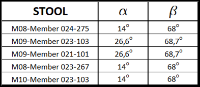
Source: Authors.
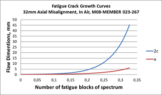
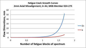
Further assessments were carried out
considering that all joints will be repaired, see Figure 7, with an axial
misalignment up to 2mm maximum. The angular misalignment and other ECA
parameters were the same as in the assessments shown in Figure 6. The results
show that after mitigation measures are undertaken to correct the axial
misalignment, all joints have acceptable fatigue lives with failure predicted
above the fatigue life of the joints represented as 1.0 in the horizontal line.
3.2 CHANGE OF THICKNESS JOINTS
Three joints, as shown in
Figure 2, were assessed to estimate their fatigue lives, subjected to the
fatigue loading spectrum for each joint and considering an existing
undetectable surface flaw located at the weld toe as reported in section 2.3,
the boundary conditions used in the ECA were the same as those used in the
cruciform joints. The EPC Group engineering team provided the fatigue variable
loads shown in Figure 8, for each of the joints investigated.
Figure
6 – Fatigue
load variable loads spectrums.
Source: Authors.
As shown Figure 2, the change of thickness joints has
presented irregular sloping in accordance with AWS D1.1/D1.1M:2010[18]. In Clause 2, item 2.26 of AWS D1.1/D1.1M:2010,
guidance is given for the thickness transition sloping of axially cyclic loaded
primary members of non-tubular joints, and there are references to the
acceptable joint configurations for the transition of butt joints in parts of
unequal thickness.
A close evaluation at the as built
geometry of the thickness transition joints under investigation shows that the
sloping prepared during manufacturing by the subcontractor did not follow the
recommendations given in AWS code D1.1/D1.1M:2010. For the sake of
illustration, figure 9 shows a paper replica of a typical change of thickness joint found on the
topsides. It can be noted that the slope prepared for the joint is in the top
side of the I-beam plate, and it is located at the smallest thickness side of the
joint. It is impossible to verify from the replica if sloping was prepared on
the thicker plate from the diamond plate side. However, according to AWS
D1.1/D1.1M:10, the slope shall be made in the thicker plate, and in this
configuration, on the underside of the plate. Figure 9 also shows an overall
underfill on the topside of the welded joint and underfill on the opposite side
of the joint.
The BS7910 gives guidance for the assessment of welded
butt joints in parts of unequal thickness, nevertheless, the fracture mechanics
parameters validated under this standard require that the joint follows sloping
configurations as in AWS D1.1/D1.1M:2010 and other similar standards. Since the
joint configuration shown in Figure 9 does not follow weld engineering best
practices, there is no ready solution in BS7910 to assess this joint. Specific
fracture mechanics parametric studies are required to make the combined
fatigue-fracture assessment in the Figure 9 joint. Although it is recognized
that a solution for this unusual joint is possible to develop, by making use of
Finite Element Assessment (FEA) techniques, other similar joints in the pancake
structures have similar preparation, with nonstandard sloping, each one of them
a different case to analyze by FEA.
This unexpected fact added difficulties in the ECA of
change of thickness joints and made the combined fatigue-fracture assessment of
these joints time consuming and costly.
Nevertheless, an alternative assessment was carried
out, considering that these joints were manufactured in accordance with the
guidance given in AWS D1.1/D1.1M:2010, with standard sloping made at the plate
with 50mm thickness.
Angular misalignments of the joints were as shown in Figure
5, and axial misalignment of a maximum 4 mm was used. All other assessment
parameters were like the assessments carried out in the stool cruciform joints.
The results of this analysis are shown in Figure 10.
Figure
7 – Fatigue-fracture
assessment results for all joints with misalignment corrected to 2mm and free
corrosion in air conditions.
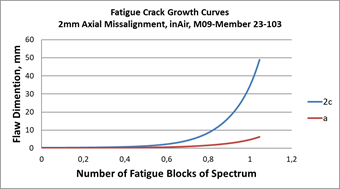
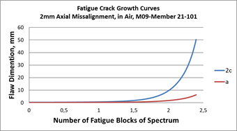
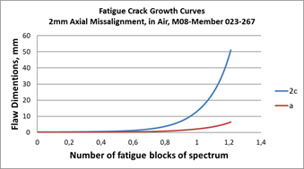
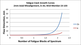
Source: Authors.
Figure
8 – Fatigue
load variable loads spectrums provided by EPC Group engineering team for the
change of thickness joints.
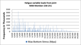
Source: Authors.
Figure
9 – Replica of
a typical thickness change welded joint.
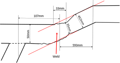
Source: Authors.
The results shown in Figure
10 lead to the conclusion that the change of thickness joint has estimated
fatigue-fracture life above the service life expected, represented by the
number 1 on the horizontal axis of the chart.
Figure
10 – Fatigue-fracture
assessment results for typical transition thickness joint, with maximum
misalignment set to 4mm.
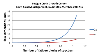
Source: Authors.
4
FURTHER ASPECTS OF THE ECA
An appraisal of non-conform structural details and an
ECA assessment were carried out in cruciform and change of thickness welded
joints from the topside structures under construction. From the results of the
appraisal, it was verified that a considerable amount of the bevel preparation,
in several types of joints, was subjected to repair work by welding buttering
layers to correct dimensional imperfections. A subcontractor of the EPC Group
carried out the work, however, there was no evidence of reporting of such
repair work and no information of the proper buttering control parameters.
Under approved and
controlled welding procedures, it is acceptable engineering best practice to
perform welding only at the required locations of the structure. It is widely
recognized that welds are the weakest link in the structural integrity of
welded components. There is much-published evidence in the open literature
demonstrating the damage caused by welding in ferritic steels, and of
particular interest for this investigation is the likelihood of introducing
planar flaws like discontinuities in the welds due to the welding operation
itself.
Buttering of bevels is an
acceptable repair technique to correct dimensional imperfections of structural
detail. However, if buttering is applied under uncontrolled circumstances it
may lead to the formation of weld flaws that are smaller than the detectable
range of the NDE techniques used to date. This may consequently leave small
discontinuities, and flaw-like defects, that will later act as fatigue crack
growth initiation points. The latter may compromise the fatigue life of the
weldments, consequently increasing the risk of fatigue failure of the welded
joints before the designed life of the structure is reached.
According to the EPC Group
quality control team, a significant number of joints manufactured by the
subcontractor had to be repaired with further buttering operation on site.
These additional repair works were necessary to eliminate welding
discontinuities found during the subcontractor's onsite inspection of bevel
preparations. However, before the EPC Group quality control team knew the
buttering made by the subcontractor, several joints were welded without any detailed
NDE of the buttered bevels. This fact led to the thought that some joints had
been assembled and welded in the topsides without assurance that the bevels
were free from any discontinuities from the early buttering operations, i.e,
there was an increasing likelihood that undetectable flaws generated at the
bevels after buttering might have remained unresolved.
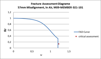
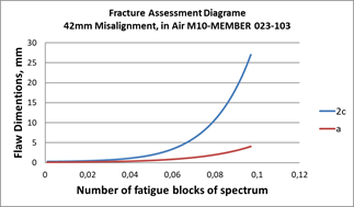
The ECA carried out in
cruciform and change of thickness welded joints has demonstrated that, in the as-built
condition, the consequences are the early structural failure of the assessed
welded joints. The assessments also show that, for the cruciform joints to
survive the imposed fatigue loads during the FPSO operation, repair work shall
be made to correct the axial misalignment of the stiffeners above the diamond
plate to a maximum of 2mm. This operation shall be performed in all stools
cruciform joints, without exception, as the driving factor for the low fatigue
life assessment is related to the increase in the stress intensity
magnification factor (Mk) due to the joint misalignment.
Fracture Mechanics-based
assessments rely on the externally driven forces (KI) calculated by equation
(1).
KI = (Ys)Ö pa Eq.
(1)
where a is
flaw height and (Ys) is a function of the applied nominal stresses, and (Ys) is calculated by
equation (2).
Ys =
M fw Mkmsmax Eq.
(2)
In equation (2) Mkm is the
stress intensity magnification factor (SIF), which depends on the geometry of the
flaw, type of welded connection, location of flaws in the weld, and local and
global dimensions of the structure.
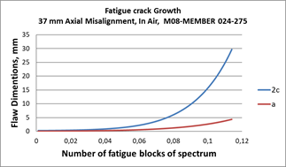
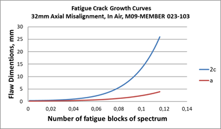
Typical initial values of Mkm
solution for the cruciform join is 1.1930 for 32mm misalignment joint and
1.1788 for the 2mm misalignment. These changes in Mkm values
associated with the bending moment stresses due to misalignment are the main
driven parameters for the significant changes in estimated fatigue crack growth
assessments reported in Figures 6 and 7.
The ECA assessment for the change of
thickness joints was only possible after considering the AWS D1.1/D1.M:2010 guidance
on thickness change sloping. Similarly, to the cruciform joints Mkm
solution plays a significant role in the assessment results. Since there is no
ready Mkm solution for nonstandard sloping butt joints and
considering that the geometric features shown in Figure 9 are widespread in the
topside structures, a Mkm solution for each joint becomes
impractical and costly.
Finally, it is necessary to perform repair
intervention to correct the geometry of the change of thickness joints to use
BS7910’s Mkm solutions, as shown in the ECA assessment in figure 10.
5
CONCLUSÕES
The following conclusions were made from the appraisal
of the non-conform structural details and the ECA assessments:
• The subcontractor
did many bevel repairs by buttering operations without properly reporting the
control parameters used in the process. This may have resulted in the formation
of unknown weld discontinuities in the repaired bevels.
• Non-NDE inspected
buttered bevels might have led to unknown welding discontinuities in the
production welds, which may have as consequence, the decrease in fatigue life
of the welded joints.
• ECA carried out
in the stool cruciform joints demonstrated the need for repair work to correct
axial misalignment to a maximum of 2mm for all topside joints.
• The change of
thickness joints has nonstandard sloping preparation in accordance with AWS
D1.1/D1.M:2010, consequently the Mkm solution provided by BS7910
could not be used for an ECA assessment.
• ECA carried out
in repaired change of thickness welded joint demonstrated that it had suitable
estimated fatigue life and a misalignment up to 4mm is tolerable.
Finally, it was recommended
that:
• Further ECA
studies be carried out in other critical welded joints of the topsides, e.g.,
columns and brace stiffening elements.
• All stiffeners
above the diamond plates in the stool cruciform joints with as-built
misalignment above 2mm shall be repositioned to guarantee the fatigue life
estimates shown in the ECA assessment.
• Nonstandard
thickness change joints, non-conform with AWS D1.1/D1.M:2010, shall be repaired
to allow reliable ECA fatigue assessment of these joints.
REFERÊNCIAS
[1] P.T. Sunang, R. Siburian, Juswan,
M.Z.M. Alie, R.N. Kaikatui, Fatigue life analysis on Floating Production
Storage and Offloading (FPSO), IOP Conf. Ser. Earth Environ. Sci. 343
(2019) 012085. https://doi.org/10.1088/1755-1315/343/1/012085.
[2] J.S. Marcos Pereira, Julian Speck, FPSO
Structural Integrity - A TWI Collection of Case Studies, in: Proc. OMAE 2004
Spec. Symp. Houst., Houston, 2004: p. OMAE-FPSO’04-0086.
https://www.twi-global.com/technical-knowledge/published-papers/fpso-structural-integrity-a-twi-collection-of-case-studies-september-2004.
[3] J.H. Kim, M.H. Kim, W.K. Moon, J. Il
Lim, S.M. Kim, K.H. Yun, Low Cycle Fatigue Evaluation for High Strength Welded
T-Joint Based on Structural Strain Method, in: Vol. 3 Mater. Technol.
Pipelines, Risers, Subsea Syst., American Society of Mechanical Engineers,
2022. https://doi.org/10.1115/OMAE2022-79765.
[4] BS 7910:2005: Guide to methods
for assessing the acceptability of flaws in metallic structures, British
Standards Institution, British Standards Institution, 2005.
[5] J. Safari, R. Thodla, I. Merchant, J.
Hamilton, Fatigue Crack Growth Rate of Reeled Pipe in Sour Environments, in:
Vol. 4 Mater. Technol., American Society of Mechanical Engineers, 2015.
https://doi.org/10.1115/OMAE2015-41028.
[6] S. Xu, W.R. Tyson, D.-M. Duan, ECA of
embedded flaws in pipeline girth welds–a review, Int. J. Press. Vessel.
Pip. 172 (2019) 79–89. https://doi.org/10.1016/j.ijpvp.2019.03.030.
[7] W. Song, Z. Man, J. Xu, X. Wang, C.
Liu, G. Zhou, F. Berto, Fatigue Crack Growth Behavior of Different Zones in an
Overmatched Welded Joint Made with D32 Marine Structural Steel, Metals
(Basel). 13 (2023) 535. https://doi.org/10.3390/met13030535.
[8] J.P. Tronskar, Heat-Affected Zone
Fracture Toughness of 420–500-MPa Yield Strength Steels: Effects of Chemical
Composition and Welding Conditions, J. Offshore Mech. Arct. Eng. 115
(1993) 66–75. https://doi.org/10.1115/1.2920092.
[9] I.H. and H.G. Pisarski, OVERVIEW OF
BS7910:2013, in: ESIA12, 12th Int. Conf. Eng. Struct. Integr.,
Manchester, UK, 2013.
https://www.twi-global.com/technical-knowledge/published-papers/overview-of-bs79102013.
[10] A. Duggal, C. Heyl, A.H. Izadparast, J.
Minnebo, Response of FPSO Systems to Squalls, in: Vol. 3 Mater. Technol. Jan
Vugts Symp. Des. Methodol. Offshore Struct. Jo Pinkster Symp. Second Order Wave
Drift Forces Float. Struct. Johan Wichers Symp. Mooring Float. Struct. Waves,
ASMEDC, 2011: pp. 913–920. https://doi.org/10.1115/OMAE2011-49855.
[11] P. Morin, P. Jean, C. Melis, Y. Helle, B.
Shepheard, Preparation and Execution of the GAP Surface Tow, in: Vol. 1
Offshore Technol., ASMEDC, 2008: pp. 587–595.
https://doi.org/10.1115/OMAE2008-57541.
[12] P. Zumpano, G. Zanon, A.G. Garmbis, L.B.
Alkmin, M.R. Richter, E.V. Oazen, P.N. Chaves, E. Hippert, Challenges About
Testing, Welding and NDT of CRA Pipelines in Brazilian Pre-Salt, in: Vol. 6
Mater. Technol. Polar Arct. Sci. Technol. Pet. Technol. Symp., American
Society of Mechanical Engineers, 2012: pp. 145–151.
https://doi.org/10.1115/OMAE2012-83461.
[13] P. Hess, S. Aksu, M. Vaz, G. Feng, L. Li,
P. Jurisic, M.R. Andersen, P. Caridis, D. Boote, H. Murayama, N. Amila, B.
Leira, M. Tammer, J. Blake, N. Chen, A. Egorov, Committee v.7 structural
longevity, 2018. https://doi.org/10.3233/978-1-61499-864-8-391.
[14] H.T. Matzkanin, George A.; Yolken,
POD/POS curves for non-destructive examination, Nondestructive Testing
Information Analysis Center, 2001.
https://apps.dtic.mil/sti/pdfs/ADA398282.pdf.
[15] G.A. Georgiou, POD curves, their
derivation, applications and limitations, Insight - Non-Destructive Test. Cond.
Monit. 49 (2007) 409–414. https://doi.org/10.1784/insi.2007.49.7.40.
[16] RESEARCH REPORT 454 – Probability of Detection (POD)
curves - Derivation, applications and limitations, British Health & Safety
Executive – HSE, first published 2006.
[17] REPORT 2000/018 – POD/POS curves for non-destructive
examination, OFFSHORE TECHNOLOGY, British Health & Safety Executive – HSE,
published in 2002, ISBN 0 7176 2297 5
[18] AWS D1.1/D1.M:2010 Structural
Welding Code – Steel, American Welding Society.